Daniel Orifice Flange Unions

DANIEL® ORIFICE FLANGE UNIONS
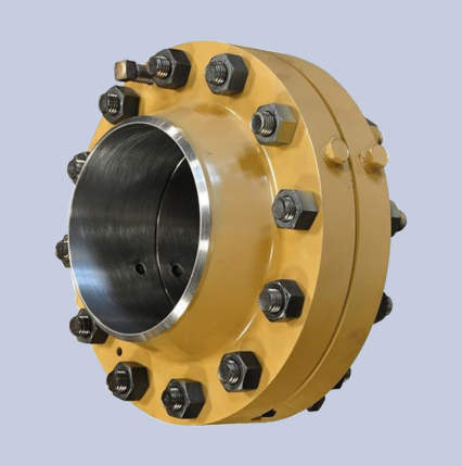
The Daniel Orifice Flange Union provides a reliable and durable solution for differential pressure flow measurement installations. Designed for long-term performance in demanding pipeline environments, these assemblies are built to deliver accurate and consistent measurement results.
Available in line sizes from 2 inches to 8 inches and pressure classes ranging from ANSI 600 to ANSI 2500, the assemblies can be supplied in either carbon steel or stainless steel to meet a wide range of application requirements.
Each unit is precision-manufactured to meet or exceed the requirements of AGA Report No. 3 and API 14.3, ensuring dependable performance and compliance with industry-recognized standards for orifice-based flow measurement.
Specifications:
- Mechanical Ratings:
- Standard: 2-in to 8-in, ANSI 600-2500, Consult factory for other options
- Mechanical Ratings: Standard: Raised face weld neck and ring-joint weld neck
- Assembly: Carbon Steel: furnished complete with studs (ASTM A-193 GR B7), nuts (ASTM A-194 GR 2H), (2) 0.0625-in non-asbestos gaskets and (2) jackscrews Stainless Steel: furnished complete with zinc-plated studs (ASTM A-193 GR B7), nuts (ASTM A-194 GR 2H), (2) 0.0625-in non-asbestos gaskets, and (2) jackscrews
- Differential Pressure Taps:
- Location and number of tap holes
- • Standard: 2 tap holes with orientation on top and bottom 180 deg apart, in accordance with API 14.3 (AGA3) or ISO 5167
- • Consult the factory for other tap locations and the number of tap options
- Process connection
- • Standard: .50-in NPT standard
- • Consult the factory for other options
- Types of tap connections
- • Standard: Threaded
- • Optional: Socket weld
- • Consult factory for other options
- Line bore tolerances
- • Standard size: Sch 40 and 80
- • Consult factory for other options
- Temperature Range:Standard: -20°F to +250°F (-29°C to +121°C)
Standard (low temperature): -100°F to +250°F (-73°C to +121°C)
Consult the factory for other options - Material Specifications:
- Standard: A105 Carbon Steel and A350 LF-2 (low temperature applications)
- Consult the factory for other options
- Flow Measurement Code: API 14.3
ISO-5167 - Design Code: ASME B16.36
- Gaskets:
- Standard gaskets for RF flanges are 0.625-in thick. (0.125-in thick gaskets are available as an option.)
- Grafoil gasket
- Spiral wound gasket without an inner ring
- Garlock gylon
- Spiral wound gasket with inner ring
- RTJ Flanges use Daniel model 560 or 590 style plate holders. The plate holder is designed with an equivalent ring gasket to match the R-number based on size and pressure class.
Applications:
- Bore Tolerances are well within the latest recommendations of API-14.3.
- Pressure Tap Hole Location is closely controlled. Tap hole centers are 0.938-in from bearing faces of raised face flanges, placing their centerline 1-in from the face of the orifice plate when a 0.063-in gasket thickness is included.
- 1. For 3-in and smaller flanges, tap location tolerance is ± 0.016-in.
- 2. For 4-in and larger flanges, tap location tolerance is ± 0.031-in.
- Pressure Tap Holes – Tap hole edges on the flange bore surface are carefully inspected to be free from burrs. All roughness is eliminated. Sizes are shown in the following tables.
- Flange Tap Connections – Standard connections are .50-in NPT. Other sizes and types are available on request.
- Gaskets – Two 0.063-in thick(1) precision die-cut gaskets are furnished with all raised face orifice flanges. Non-asbestos gaskets are standard.